Questions about the safety wirings
-
Basicmicro Support

- Posts: 1594
- Joined: Thu Feb 26, 2015 9:45 pm
Re: Questions about the safety wirings
The diagrams in the User Manual are made to be as simple as possible to show the concept. However there are many ways to wire up the pre-charge circuit.
The diagram shows the main power switch witha resistor across the switch. The pre-charge resistor is in circuit all the time with this circuit. This is fine if you are using batteries and unplug the batteries when you are done. If, however you want to have power perminently attached you would need something more complex.
In general I dont think you can find a 3 poll switch that can handle main power current levels so the next simplest setup would be to have a small switch for the pre-charge resistor and a second large switch/contactor for the main power. Then you would have to power on the pre-charge, wait for some time(seconds or less), then turn on the main power switch.
The main power switch COULD be the emergency cut off or you could use a dedicated emergency cutoff button(like on indurstrial equiment).
The diode in the diagrams is used as a path back to the battery in the even main power is cut off while the motors are running. This provides a path for regen energy from the motors to get back to the battery instead of frying the electronics. I recommend the diode by pass all main power switches/fuses not just the one main power switch.
-
cyberdemon
- Posts: 10
- Joined: Sun Oct 08, 2017 3:41 am
Re: Questions about the safety wirings
nschoe, the reason the pre-charge resistor doesn't fry is due to voltage drop. In order to drive 5A through a 220Ohm resistor, you would need 1100 Volts (!).
Since your battery can only supply (say) 24V, then a maximum of 0.11A can flow through your resistor, dissipating 2.4W (which is still quite a lot for a resistor).
As a precaution, you can buy self-fusing resistors, which are guaranteed to fail open-circuit rather than catching fire.
In the case of the switch opening, the MCP would either shut down (because it requires more than 0.1A for its logic) or else raise an 'under-voltage' error due to the voltage drop across the resistor. It cannot drive 5A through the motors with the switch open.
-
Basicmicro Support
- Posts: 1594
- Joined: Thu Feb 26, 2015 9:45 pm
Re: Questions about the safety wirings
Cyberdemon, thanks for expanding on the pre-charge resistor power disipation.
As Cyberdemon said the pre-charge resistor by itself cant power a motor. Also as he said the current is limited to a maximum of battery voltage/220. ALso since the precharge is primarily charging the DC Bus caps as these charge the current draw will be reduced till it reaches near zero. Down to around 30ma which is the draw from the logic of the Roboclaw.
As Cyberdemon said the pre-charge resistor by itself cant power a motor. Also as he said the current is limited to a maximum of battery voltage/220. ALso since the precharge is primarily charging the DC Bus caps as these charge the current draw will be reduced till it reaches near zero. Down to around 30ma which is the draw from the logic of the Roboclaw.
Re: Questions about the safety wirings
This is one example that may help. Here is how I have done this with my design, which is most likely different than yours. I am expecting stall conditions on 1000W max rated motors (40+ Amps at 24V DC - each motor) so finding a circuit that suits the need for safety is a must. I am using an MCP263 motor controller.
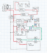
In the first photo: This is my basic circuit diagram For the switch with the safety resistor I am using an aluminum 5watt 5ohm power resistor (green), and a "Constant Current - High Current Relay" (metal can). It is important to use a "Constant Current Relay", and not a momentary one that is normaly used on automotive starters. I also use a battery cut-off key to cut power before the relay. In the schematic I have the section labeled "IonMC Protection circuit", this is the relay and resistor.
NOTE: right click images and open in new tab or window for full size.
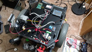
In the second photo is the way it is actualy wired, I am using 8awg wire for all high current circuits but should be using 4awg that I could not find. The green resistor, lower right, is now connected to the left and right side of the high current relay, metal can same area of image, but is not connected in this image.
Hope this helps getting your project up and running safely.
In the first photo: This is my basic circuit diagram For the switch with the safety resistor I am using an aluminum 5watt 5ohm power resistor (green), and a "Constant Current - High Current Relay" (metal can). It is important to use a "Constant Current Relay", and not a momentary one that is normaly used on automotive starters. I also use a battery cut-off key to cut power before the relay. In the schematic I have the section labeled "IonMC Protection circuit", this is the relay and resistor.
NOTE: right click images and open in new tab or window for full size.
In the second photo is the way it is actualy wired, I am using 8awg wire for all high current circuits but should be using 4awg that I could not find. The green resistor, lower right, is now connected to the left and right side of the high current relay, metal can same area of image, but is not connected in this image.
Hope this helps getting your project up and running safely.
Re: Questions about the safety wirings
I looked at your circuit diagram and photo. Just two more things you should do to make the power distribution be "best practice". One rule is that the purpose of a fuse is to protect the wires from overheating should that be damage that causes a short.
SO while the battery is a high amp fuse, none of your branches are fused. For example, the 3.5 amp 5V supply is fused only by the large amp fuse. At the wires that go to the 3.5 amp supply large enough not to melt before that large fuse blows. SO if you have only one 60A fuse then ALL of your wires need to be #6 cable. A better solution is a fuse box with multiple smaller fuses. My robot also uses a DC/DC supply to power a Rasburry Pi and that DC/DC supply is fed from a 5 amp fuse by #20 wires, using conectors rates for only a few amps.
Using a fuse box will save you money and space because then you most wire runs and most connectors can use much small size parts.
Next: Best engineering practice is to contain the batteries in a box and INSIDE (must be inside) the box is the main battery fuse and a disconnect switch. Any wires leading outside the box are protected with the fuse and switch. The fuse is selected to protect the size of the wire used.
I broke the above rule a year or so ago and instantly vaporized a #6 wire. This opened the circuit just like a fuse and nothing except my fingers was damaged. Fingers recovered in a few days. The noise was impressive. Peole in other rooms noticed. But once the fuze in inside the box the system is safe even from dead shorts
BTW, it can be serious. In a diesel mechanics class, the instructor made a video of a crescent wrench being placed across terminals of an engine starting battery, the wrench was blown apart. (camera was placed behind a plexiglass shield.)
Many lipo batties used in larger robots can provide the same currents as that diesel truck battery.
I assume all your wires get covered. I find that tree branches and what not find their way to catching on any exposed wire.
That said, it will still work fine if you ignore all the safety rules and build with hot glue and rubber bands, As long as you never sell this as a product. You will never sue yourself.
-
Basicmicro Support
- Posts: 1594
- Joined: Thu Feb 26, 2015 9:45 pm
Re: Questions about the safety wirings
Just wanted to add, that the power rating of the pre-charge resistor doesnt need to be for continous current It will only need to handle the wattage during the charge period(less than 1 second to a couple seconds depending on the resistance and voltage you use). In general resistors wattage rattings are for continous power and can be overdriven by a significant amount for brief periods.